Arduino GPS Tracker Project Tutorial Build Your Own
Arduino GPS tracker project tutorial provides a comprehensive guide to building your own GPS tracking device. Learn the basics of Arduino GPS trackers, including their applications and essential components. This tutorial covers everything from hardware setup and software development to data processing and visualization. We’ll also explore advanced features, troubleshooting tips, and project examples, making it a complete learning resource.
The tutorial will take you step-by-step through the process of creating a functional GPS tracker using an Arduino board. From connecting the GPS module to the Arduino, to writing the necessary code and visualizing the data, this guide is designed for both beginners and experienced makers. You will learn how to use the Arduino IDE to program the tracker, receive and format GPS data, and even display the data on a map.
Real-world applications and design considerations are also discussed to broaden your understanding of the possibilities.
Introduction to Arduino GPS Tracking
Arduino GPS trackers are increasingly popular for a wide array of applications, from asset tracking and vehicle monitoring to personal safety devices and environmental monitoring. These devices use readily available and relatively inexpensive hardware components combined with user-friendly programming environments to provide a practical and affordable solution for real-time location data. The versatility of Arduino platforms makes them suitable for various tracking needs, catering to diverse project requirements.These devices essentially act as miniature location-aware systems.
They receive GPS signals to pinpoint their current location, store that data, and often transmit it to a central location or platform for monitoring. This allows users to track the movement of assets or individuals, monitor the health of equipment, or simply know the location of a person in distress.
Basic Components of a Simple GPS Tracker
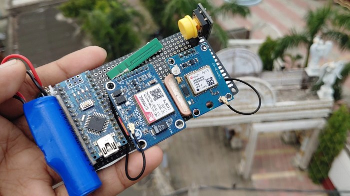
The core components for a basic GPS tracker typically include a GPS module, an Arduino microcontroller board, and a power source. The GPS module receives and interprets satellite signals to determine the device’s position. The Arduino board acts as the central processing unit, handling data acquisition, storage, and communication. A power source, like a battery, provides the necessary energy for the device to function.
Types of GPS Modules
Several GPS modules are compatible with Arduino boards. The most common types include the u-blox, the Adafruit, and the SparkFun. Each module differs in terms of features, performance, and price. Factors to consider when choosing a GPS module include accuracy, communication protocol (like serial), and power consumption.
Essential Programming Concepts for GPS Tracking
The Arduino programming language plays a critical role in making the GPS tracker functional. Core concepts include reading data from the GPS module, formatting and storing the location data, and communicating that data to a receiver (potentially via a cloud platform or another device). Libraries specifically designed for GPS modules simplify the process of interacting with the hardware. Proper error handling is crucial for robust GPS tracking, as issues like satellite lock loss can cause data gaps.
Data Acquisition and Processing Flowchart
The following flowchart illustrates the stages involved in data acquisition and processing within a GPS tracker:
Start -->
|
V
GPS Module Receives Satellite Signals -->
|
V
Data Processed by GPS Module -->
|
V
Data Transmitted to Arduino -->
|
V
Arduino Stores Data (e.g., Latitude, Longitude) -->
|
V
Data Formatted for Transmission -->
|
V
Data Sent via Serial Communication (or other method) -->
|
V
Data Received by External Device/Platform -->
|
V
Data Displayed or Stored -->
|
V
End
The flowchart Artikels the sequential process, from initial signal reception to final data display or storage, highlighting the key steps in a simple GPS tracker application. Real-world applications often involve additional steps, such as data logging, storage, and security protocols.
Hardware Setup and Connection: Arduino GPS Tracker Project Tutorial
Setting up the hardware is a crucial step in building your Arduino GPS tracker. Proper connections ensure the GPS module communicates effectively with your Arduino board, allowing accurate location data acquisition. This section details the wiring procedures, power supply needs, and antenna considerations for a reliable GPS tracking system.
Connecting the GPS Module to the Arduino
The GPS module needs to be connected to the Arduino board via several wires. Correct pin-to-pin connections are essential for successful data transmission and reception. The process involves connecting the power, ground, and serial communication lines. Carefully following the wiring diagram for your specific GPS module is vital to avoid potential damage.
Wiring Diagrams for Different GPS Modules
Various GPS modules have slightly different pinouts. It is critical to refer to the manufacturer’s datasheet for your specific GPS module. This document usually provides a detailed wiring diagram, showing the connections between the GPS module’s pins and the Arduino board’s pins. Several diagrams may exist online for different models.
Power Supply Requirements
The GPS module requires a stable power supply for proper operation. The specific voltage requirements vary between modules, typically ranging from 3.3V to 5V. It is important to match the power supply voltage to the GPS module’s specifications. Overvoltage or undervoltage can cause erratic behavior or damage the module. Ensure the power supply is sufficient to handle the combined current draw of the GPS module and the Arduino board.
Antenna Selection and Placement
A high-quality antenna is essential for optimal GPS signal reception. The antenna should be chosen based on its gain, frequency range, and size. External antennas are often used for improved signal strength. Proper antenna placement is equally important. The antenna should be positioned in an open area with minimal obstructions.
This usually involves mounting the antenna externally, away from metallic objects, and ensuring a clear line of sight to the sky. Placement in a window or rooftop location is often preferred for enhanced signal reception. The type of antenna (e.g., whip, PCB) and its orientation will depend on the specific GPS module.
Pin Connections for a Specific GPS Module (Example)
This table demonstrates the typical pin connections for a common GPS module. Note that these connections may vary depending on the specific module. Always consult the module’s datasheet for accurate pinouts.
| Arduino Pin | GPS Module Pin | Description |
|---|---|---|
| 5V | VCC | Power supply |
| GND | GND | Ground |
| RX | TX | Serial receive |
| TX | RX | Serial transmit |
Software Development (Arduino IDE)
Getting your Arduino GPS tracker up and running involves installing and configuring the Arduino Integrated Development Environment (IDE). This crucial step allows you to write and upload the code that will communicate with your GPS module and process the data it transmits. The Arduino IDE is a free and user-friendly software platform designed specifically for programming Arduino boards.
The Arduino IDE provides a comprehensive environment for writing, compiling, and uploading code to your Arduino board. It’s a crucial tool for any project involving Arduino microcontrollers, and this section will walk you through its setup and usage for your GPS tracker.
Installing and Setting Up the Arduino IDE
The Arduino IDE can be downloaded from the official Arduino website. The installation process is straightforward and generally compatible with various operating systems. Follow the on-screen instructions during installation. After installation, ensure the IDE is properly configured to recognize your Arduino board. You’ll need to select the correct board type (e.g., Arduino Nano, Arduino Uno) and port from the IDE’s menu options.
Initializing the GPS Module
Initializing the GPS module involves setting up the communication parameters. This typically involves configuring the baud rate, which dictates the speed of communication between the Arduino and the GPS module. A common baud rate is
9600. The code below exemplifies how to initialize the GPS module using the SoftwareSerial library, essential for serial communication over non-standard pins:
“`C++
#include
SoftwareSerial GPSSerial(10, 11); // RX, TX
void setup()
Serial.begin(9600);
GPSSerial.begin(9600);
“`
Receiving GPS Data
The GPS module transmits data in a specific format. The code must parse this data to extract latitude, longitude, and time information. Libraries like the TinyGPSPlus library facilitate this process. The following code snippet demonstrates how to read data from the GPS module and store it into variables:
“`C++
#include
TinyGPSPlus gps;
void loop()
while (GPSSerial.available() > 0)
if (gps.encode(GPSSerial.read()))
if (gps.location.isValid())
latitude = gps.location.lat();
longitude = gps.location.lng();
if (gps.time.isValid())
currentTime = gps.time.hour();
“`
Formatting and Displaying GPS Data
Formatting GPS data into a user-friendly format, like displaying latitude and longitude with degrees, minutes, and seconds, enhances readability. Serial.print statements are utilized for outputting the collected GPS data to the computer or a serial monitor. Formatting data enhances readability and interpretation:
“`C++
void loop()
// … (previous code)
if (gps.location.isValid())
Serial.print(“Latitude: “);
Serial.print(gps.location.lat(), 6);
Serial.println(” degrees”);
Serial.print(“Longitude: “);
Serial.print(gps.location.lng(), 6);
Serial.println(” degrees”);
“`
GPS Data Fields
The table below Artikels the common data fields provided by a GPS module, crucial for understanding the output of the tracker.
| Data Field | Description |
|---|---|
| Latitude | The geographic coordinate specifying north-south position. |
| Longitude | The geographic coordinate specifying east-west position. |
| Time | The current time, typically in UTC format. |
| Date | The current date, often in a specified format. |
| Altitude | The elevation above sea level. |
| Speed | The current speed of the GPS receiver. |
| Course | The direction of travel. |
Data Processing and Transmission
The Arduino GPS tracker needs to process the raw GPS data received and transmit it effectively. This involves extracting crucial information, storing it persistently, and sending it to a central location for monitoring. Robust data handling is essential for accurate tracking and timely alerts.
Effective parsing of the GPS data stream is vital for extracting usable information. The GPS module typically outputs a string of data that needs to be meticulously parsed to extract the latitude, longitude, time, and other relevant parameters. Specialized libraries and techniques simplify this process, allowing you to focus on data utilization rather than intricate parsing routines.
GPS Data Parsing
Extracting relevant data from the raw GPS output is a crucial first step. A parser, often implemented as a function, meticulously dissects the incoming string. This function typically searches for delimiters, extracts substrings representing latitude, longitude, and time, and converts these strings into numerical values. Accurate conversion is critical for subsequent calculations and storage. Error handling is also a vital part of the parsing process.
Unexpected or incomplete data needs to be identified and handled appropriately. A common approach involves checking the validity of extracted data, such as the range of latitude and longitude values.
Data Storage and Logging
Reliable data storage is essential for tracking and analysis. The GPS coordinates and timestamps need to be logged persistently. One common method involves using the Arduino’s onboard flash memory to store data in a structured format. The format should allow easy retrieval of data, ensuring the system can access previous positions. Alternatively, external storage devices, like SD cards, can be used for more extensive logging, accommodating larger amounts of data.
Choosing the appropriate storage method depends on the expected volume of data and the required retention period.
Serial Data Transmission
Transmitting the processed GPS data is another crucial aspect of the tracker. Serial communication is a widely used method. The Arduino’s serial communication interface sends the extracted data as a structured string, typically separated by delimiters. This string format should be consistent and easily parsed by the receiving application. The data string might contain the latitude, longitude, timestamp, and potentially other relevant information.
Communication Protocols
| Protocol | Description | Advantages | Disadvantages |
|---|---|---|---|
| Serial Communication (e.g., UART) | Simple, widely supported by Arduino and other devices. | Ease of implementation, low cost, common standard. | Limited bandwidth, prone to errors over long distances. |
| Bluetooth | Wireless communication with a range of several meters. | Wireless connectivity, better range than serial. | Requires Bluetooth module, potential power consumption. |
| Cellular (e.g., GSM, GPRS) | Transmission over cellular networks for long-range communication. | Large range, reliable in most areas. | Higher cost, requires a cellular module. |
Selecting the right protocol depends on factors like the desired range, cost, and required reliability.
Error Handling During Transmission
Robust error handling is essential to maintain data integrity. Methods for checking data integrity during transmission include checksums or error detection codes. These ensure that the received data matches the transmitted data. Error handling routines should include checks for missing data, corrupted data, or communication failures. Implement strategies to retry transmission if errors occur.
The system should log errors and provide mechanisms for reporting or alerting to the user in case of continuous failures.
Displaying and Visualizing Data
Visualizing the GPS data collected by your Arduino tracker is crucial for understanding its movement patterns and for effective monitoring. A clear representation of location, time, and trajectory makes the data actionable and insightful. This section details various methods to display and visualize the GPS coordinates, including map integration and data logging.
Graphical User Interface (GUI) for Data Display
A graphical user interface (GUI) provides a user-friendly way to view GPS coordinates in real-time. Several software options are available, including custom-built applications and readily available libraries. These interfaces allow you to display the latitude and longitude values, often in conjunction with a map, to provide a clear visual representation of the tracked object’s movement.
Creating Maps with GPS Coordinates
Several libraries and platforms offer convenient map integration. Using the GPS coordinates received from your Arduino, you can plot the data points on a map. This allows you to visualize the movement path of the tracked object. Popular choices include libraries specifically designed for map rendering within your GUI.
Logging and Storing Data for Analysis
Data logging is essential for future analysis and reporting. Storing the GPS coordinates, timestamps, and other relevant data enables you to track trends, patterns, and potentially even predict future movements. Data storage can be in a variety of formats, such as CSV files or database entries, depending on the chosen software or libraries. This stored data can be further analyzed using spreadsheet software or dedicated mapping applications.
Example data formats could include latitude, longitude, timestamp, and potentially additional sensor readings.
Using Libraries for Enhanced Visualization
Several libraries provide enhanced visualization capabilities, making it easier to plot and interpret the data. These libraries often handle map rendering, data plotting, and user interaction seamlessly, improving the overall user experience and the clarity of the visualization. Some popular libraries support different map providers (like Google Maps, OpenStreetMap) and allow for customization of the display.
Plotting Data on a Map, Arduino GPS tracker project tutorial
Plotting the GPS data on a map is a crucial step in visualizing the tracker’s movements. The process involves converting the latitude and longitude coordinates into map coordinates, which can then be displayed on the map. A typical workflow includes receiving the GPS data, parsing it, converting the coordinates to map coordinates, and displaying the path on the map.
Plotting the GPS data on a map involves transforming the latitude and longitude coordinates into map coordinates that are suitable for the chosen map visualization library. The path is then plotted using these coordinates.
Tools like Google Maps API or other map visualization libraries often provide functions for this purpose, simplifying the process. Libraries often provide methods for creating markers at specific locations and drawing lines to connect consecutive points, visualizing the trajectory. The resulting visualization will show the tracked object’s movement across a map, offering a clear picture of its journey.
Advanced Features and Enhancements
Taking your Arduino GPS tracker to the next level involves incorporating real-time tracking, cloud integration, remote monitoring, alerts, and enhanced accuracy. These features significantly expand the capabilities of your project, transforming it from a basic location logger to a powerful tracking and monitoring system.
Real-Time Tracking Capabilities
Real-time tracking provides constant updates on the device’s location, enabling immediate awareness of its movement. This is achieved by transmitting location data at regular intervals. The frequency of these updates directly impacts battery life and data bandwidth usage. A balance must be struck between real-time responsiveness and battery efficiency. For example, a tracking application for livestock might require frequent updates to monitor grazing patterns, while a vehicle tracker might use less frequent updates to minimize energy consumption.
Cloud Platform Integration for Data Storage
Cloud platforms offer robust data storage solutions and enable remote access to your data. Popular platforms include Firebase, ThingSpeak, and AWS IoT Core. These platforms handle the complexities of data storage, retrieval, and visualization, allowing you to focus on the core functionality of your tracker. Cloud integration also unlocks opportunities for data analysis and reporting. For instance, analyzing historical location data can provide insights into vehicle maintenance needs or livestock herd movements.
GSM/GPRS Modules for Remote Monitoring
GSM/GPRS modules enable remote monitoring by utilizing cellular networks. They provide a communication channel to send and receive data outside the local network, offering crucial advantages. For example, if your tracker is in a remote area without Wi-Fi, GSM/GPRS allows for data transmission. This functionality is critical for applications requiring remote control or alerts, such as monitoring assets in remote locations.
Location-Based Alerts and Notifications
Location-based alerts and notifications enhance the functionality of your tracker by triggering actions based on predefined criteria. For example, you can set up alerts for exceeding predefined boundaries, enabling you to take swift action. If a package is being delivered, a geofence alert could notify the recipient when the package reaches a certain location. This is a useful feature for applications requiring timely interventions or notifications.
Improving Accuracy and Reliability
Several techniques can enhance the accuracy and reliability of your GPS tracker. Calibration of the GPS module and the use of a robust antenna are crucial for accurate location data. Employing techniques like averaging multiple GPS readings can reduce errors and enhance the reliability of location data. For instance, a tracker monitoring a delivery vehicle’s route could use multiple readings to ensure the accuracy of the route.
Implementing error handling in your code is vital to ensure the tracker functions consistently in various conditions. This includes accounting for potential GPS signal loss or other errors. Data validation is also essential for identifying and correcting any discrepancies in the transmitted data.
Troubleshooting and Common Issues
Source: diyprojectslab.com
Developing an Arduino GPS tracker involves several potential pitfalls. Understanding common problems and their solutions is crucial for successful project completion. Thorough troubleshooting ensures accurate data collection and reliable tracking performance.
Effective debugging relies on systematic analysis of the issue, starting with the simplest possible explanations and gradually increasing complexity as needed. This methodical approach allows for efficient identification and resolution of the problems encountered during the development process.
Connectivity Problems
Connectivity problems are frequent during GPS tracking projects. Several factors can cause issues with the GPS module’s connection to the Arduino board. These issues may stem from improper wiring, inadequate power supply, or conflicting communication protocols.
- Incorrect Wiring: Ensure all connections are secure and follow the GPS module’s datasheet. Double-check the GND, VCC, and RX/TX pins are correctly connected to the Arduino’s corresponding pins. A visual inspection of the wiring can reveal potential issues like loose connections or mismatched pin assignments.
- Insufficient Power Supply: A weak power supply can lead to intermittent or unreliable communication. Use a stable power source to prevent voltage fluctuations that can cause communication problems. Check the power requirements of both the GPS module and the Arduino board to ensure compatibility.
- Interference: Electronic interference from other devices or components can disrupt the GPS signal. Position the GPS module away from potential sources of interference, such as high-powered electrical equipment or strong radio signals.
- Incorrect Serial Communication Settings: Ensure the baud rate used in the Arduino code matches the settings on the serial monitor. Mismatched baud rates result in data loss and communication failure.
Data Accuracy Issues
Achieving precise location data is essential in GPS tracking applications. Various factors can affect the accuracy of the data, including signal strength, satellite visibility, and environmental conditions.
- Signal Strength: Obstructions, such as buildings, trees, or dense foliage, can weaken the GPS signal, leading to inaccurate location data. Open areas with clear views of the sky are optimal for GPS reception. Proper antenna placement can significantly improve signal strength.
- Satellite Visibility: The number of visible satellites affects the accuracy of location determination. Positioning the device in an area with good satellite visibility is crucial for accurate data. Areas with significant obstructions or dense structures may have reduced satellite visibility, potentially leading to inaccuracies.
- Environmental Factors: Weather conditions, such as heavy rain or snow, can interfere with the GPS signal, affecting the accuracy of location data. Similarly, high-altitude environments can present unique challenges to GPS reception.
Debugging Arduino Code
Effective debugging involves systematically checking the Arduino code for errors. This systematic approach helps isolate the source of problems and ensures efficient code correction.
- Serial Monitor: Use the Arduino IDE’s serial monitor to print out the values of important variables during runtime. This real-time output can help pinpoint issues in data transmission, calculations, or sensor readings.
- Print Statements: Strategically place print statements within your code to output the values of variables at different stages of execution. This helps track the flow of data and identify points where data is not being processed correctly.
- Breakpoints: Employ breakpoints in your code to pause execution at specific points during runtime. This allows for inspection of variable values and helps identify the source of errors.
- Code Reviews: Have another person review your code to catch potential logical errors or syntax issues that might be missed during self-assessment. A fresh perspective can often reveal problems in the code’s logic or implementation.
Antenna Placement and Signal Reception
Optimizing antenna placement is critical for maximizing GPS signal reception. Factors like orientation and surrounding environment influence the effectiveness of the antenna.
- Antenna Placement: Position the antenna in a location with minimal obstructions to the sky. Avoid placing the antenna near metal objects or other sources of interference. Properly mounting the antenna, such as on a raised platform, can improve signal reception.
- Antenna Orientation: Ensure the antenna is properly oriented to maximize signal reception. This may involve adjusting the antenna’s angle to align with the satellite signals.
- Antenna Type: Selecting an appropriate antenna type for the specific environment is essential. Different antenna types have varying sensitivity and performance characteristics.
Project Examples and Case Studies
Real-world applications of Arduino GPS trackers are diverse and impactful. From asset tracking to personal safety, these systems offer valuable data for improved efficiency and security. This section delves into specific projects, showcasing the versatility and practical application of Arduino-based GPS tracking.
Complete Arduino GPS Tracker Project
This project Artikels a comprehensive Arduino GPS tracker for monitoring the location of a package in transit. The tracker utilizes an Arduino Nano, a GPS module, and a GSM module for communication. The Arduino Nano receives GPS coordinates and transmits them via the GSM module to a cloud-based platform. This platform allows real-time monitoring of the package’s location, enabling users to track its movement and estimated time of arrival.
Key features include: power management for extended battery life, robust error handling for GPS signal loss, and a user-friendly web interface for viewing data.
Specific Application of Arduino GPS Tracking: Livestock Monitoring
A significant application of Arduino GPS tracking is livestock monitoring. Farmers can deploy GPS trackers on animals to monitor their location, movement patterns, and overall health. This data can provide insights into grazing patterns, herd behavior, and potential health issues. Real-time tracking enables proactive intervention, reducing risks associated with livestock loss or illness. For example, a farmer could track the movement of their sheep during grazing hours to ensure they’re staying in the designated area.
The system would also alert the farmer if an animal strays from the herd or experiences unusual movement.
Comparison of Arduino GPS Tracker Projects
Different Arduino GPS tracker projects can vary significantly in complexity and functionality. A basic project might focus solely on location tracking, while a more advanced system could incorporate additional sensors like temperature or acceleration. A comparison could be structured by focusing on the targeted application (e.g., vehicle tracking vs. personal safety), the communication method (e.g., cellular vs. Wi-Fi), and the level of data processing.
Factors to consider during comparison include cost, power consumption, accuracy, and ease of implementation. For instance, a project for tracking a vehicle might prioritize high-speed data transmission via cellular, while a personal safety tracker might rely on a lower-cost, lower-bandwidth method like Wi-Fi.
Real-World Applications for Arduino GPS Trackers
- Asset Tracking: Monitoring the location of equipment, tools, or vehicles in real-time, crucial for logistics and supply chain management. This is especially useful for companies needing to track the movement of large shipments or expensive machinery.
- Personal Safety: Providing real-time location data for individuals in need of assistance, such as hikers or elderly people. This enhances safety by allowing for quick response in emergency situations.
- Fleet Management: Tracking the location and activity of vehicles in a fleet, enabling efficient routing, fuel optimization, and driver performance monitoring. This could be applied to delivery services or public transportation.
- Wildlife Tracking: Monitoring the movement of animals, aiding in research and conservation efforts. This allows for the study of animal behavior and migration patterns, critical for preserving endangered species.
- Agricultural Monitoring: Tracking the location of livestock or agricultural equipment, optimizing resource use and improving efficiency. This can be used to monitor the position of tractors and other machinery on a farm.
Design Considerations for Different GPS Tracker Applications
Factors like power consumption, communication range, and data processing requirements vary significantly based on the application. For example, a tracker designed for a small, portable device (e.g., a personal safety tracker) must prioritize low power consumption. Conversely, a system for a large vehicle might require robust communication protocols to handle higher data volumes and distances. Other important considerations include:
- Battery Life: Critical for applications requiring extended operation without recharging, especially for remote devices.
- Accuracy: High accuracy is essential for precise location determination in applications such as asset tracking or emergency response.
- Cost-Effectiveness: Balancing the cost of components with the desired functionality and performance.
- Security: Protecting transmitted data to prevent unauthorized access or manipulation.
Closure
In summary, this Arduino GPS tracker project tutorial provides a practical approach to building your own GPS tracking system. We covered various aspects, from the fundamental hardware connections to the sophisticated data visualization techniques. By the end of this tutorial, you will be equipped with the knowledge and skills to build and customize your own GPS tracker for diverse applications.
Troubleshooting and project examples will reinforce your learning and provide a solid foundation for future projects.









Post Comment